


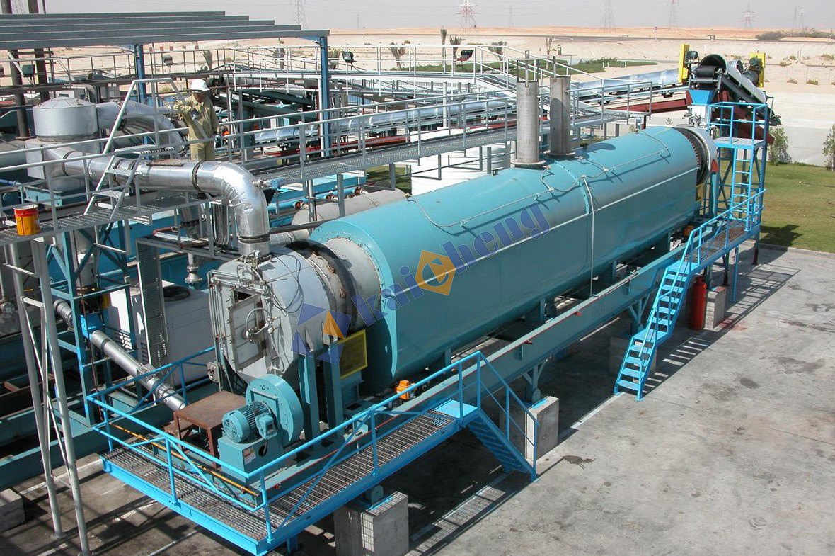


Spiral Plate Heat Exchanger
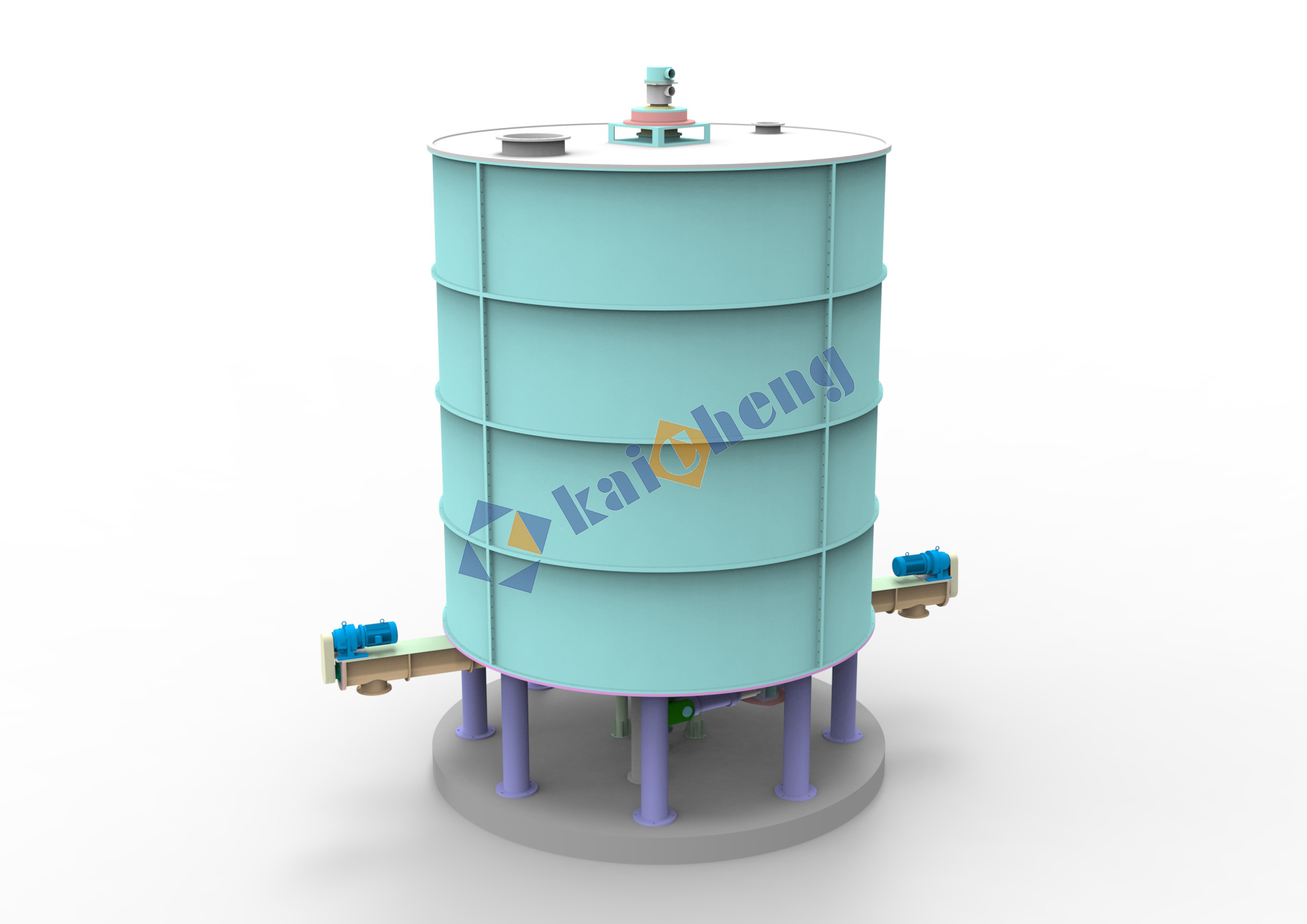
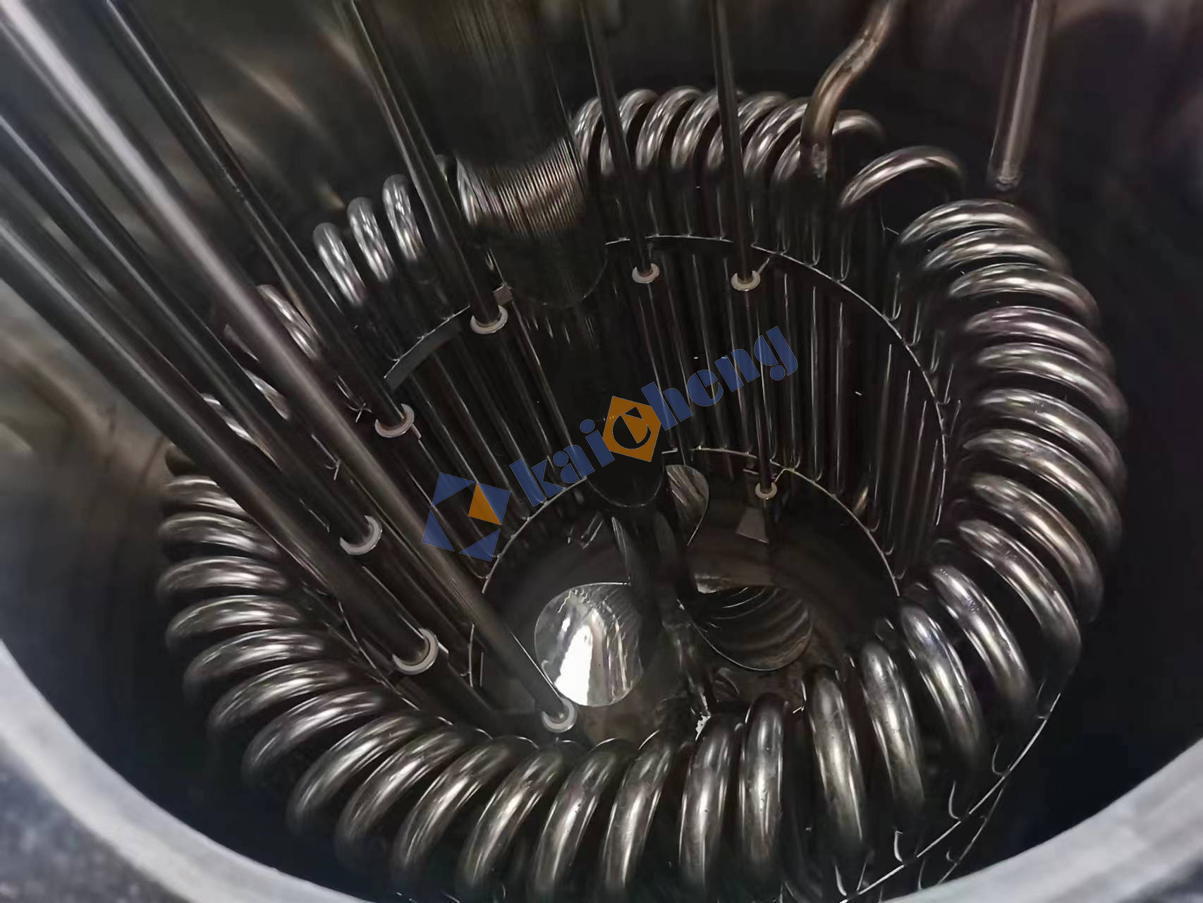
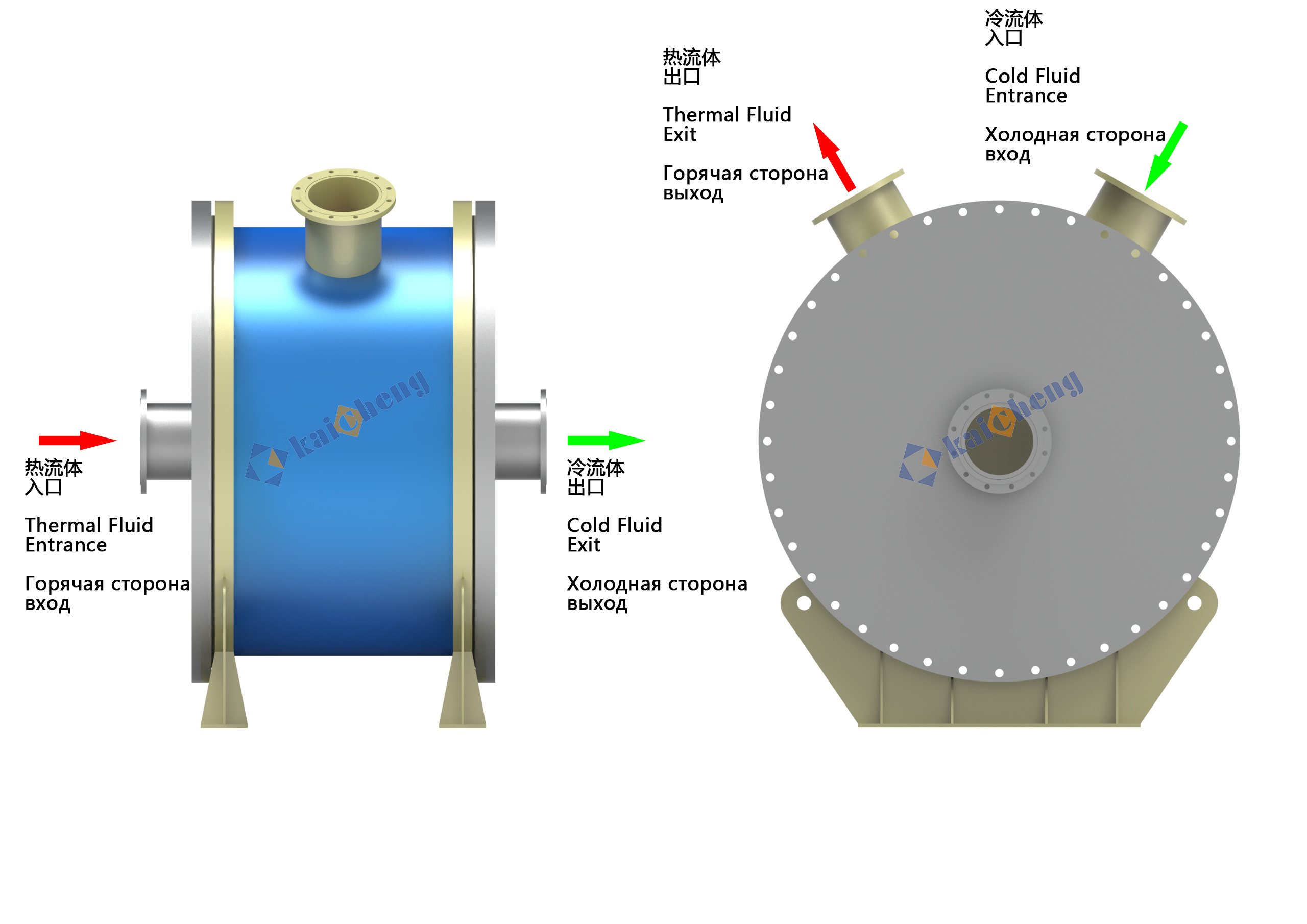
The spiral heat exchanger has a double flow channel composed of two concentric spiral lines. The double flow channels do not interfere with each other, and the medium is in a completely counter-flow state in the flow channel. Thermal fluid generally enters from the central axis, flows from the inside to the outside, and flows out from the sides. The cold fluid enters from the outside of the side and flows inward toward the central axis to achieve counterflow. This method can achieve higher heat transfer coefficients than other types of heat exchangers. Easier to achieve temperature exchange.

Product Attachments:
Keywords: Spiral Plate Heat Exchanger
- Description
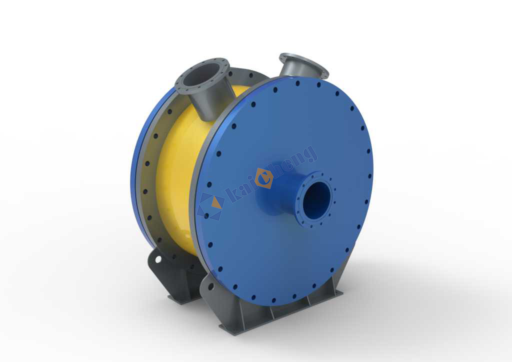
- Schematic Diagram
- Parameter
- Result
-
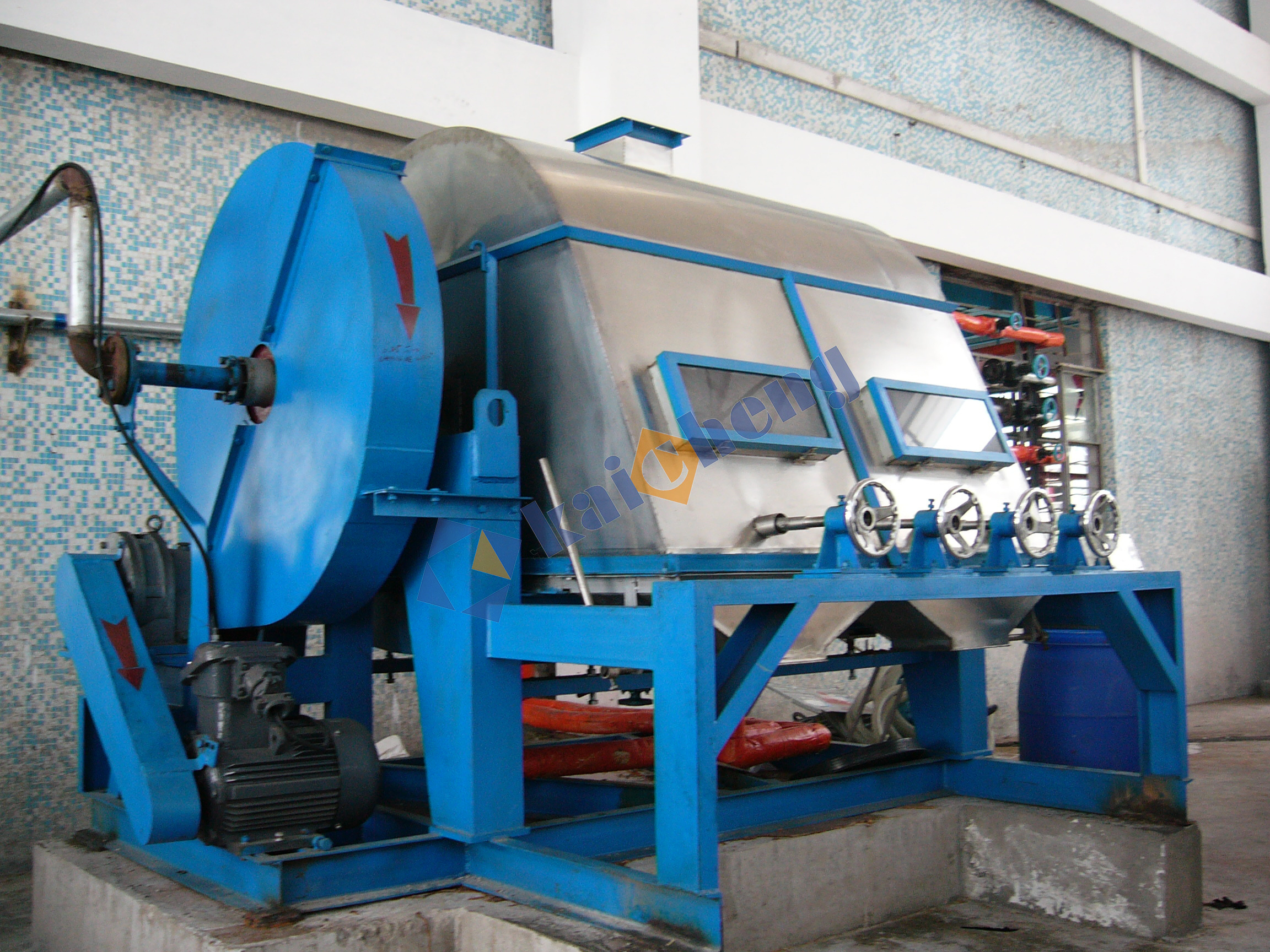
Equipment Introduction:
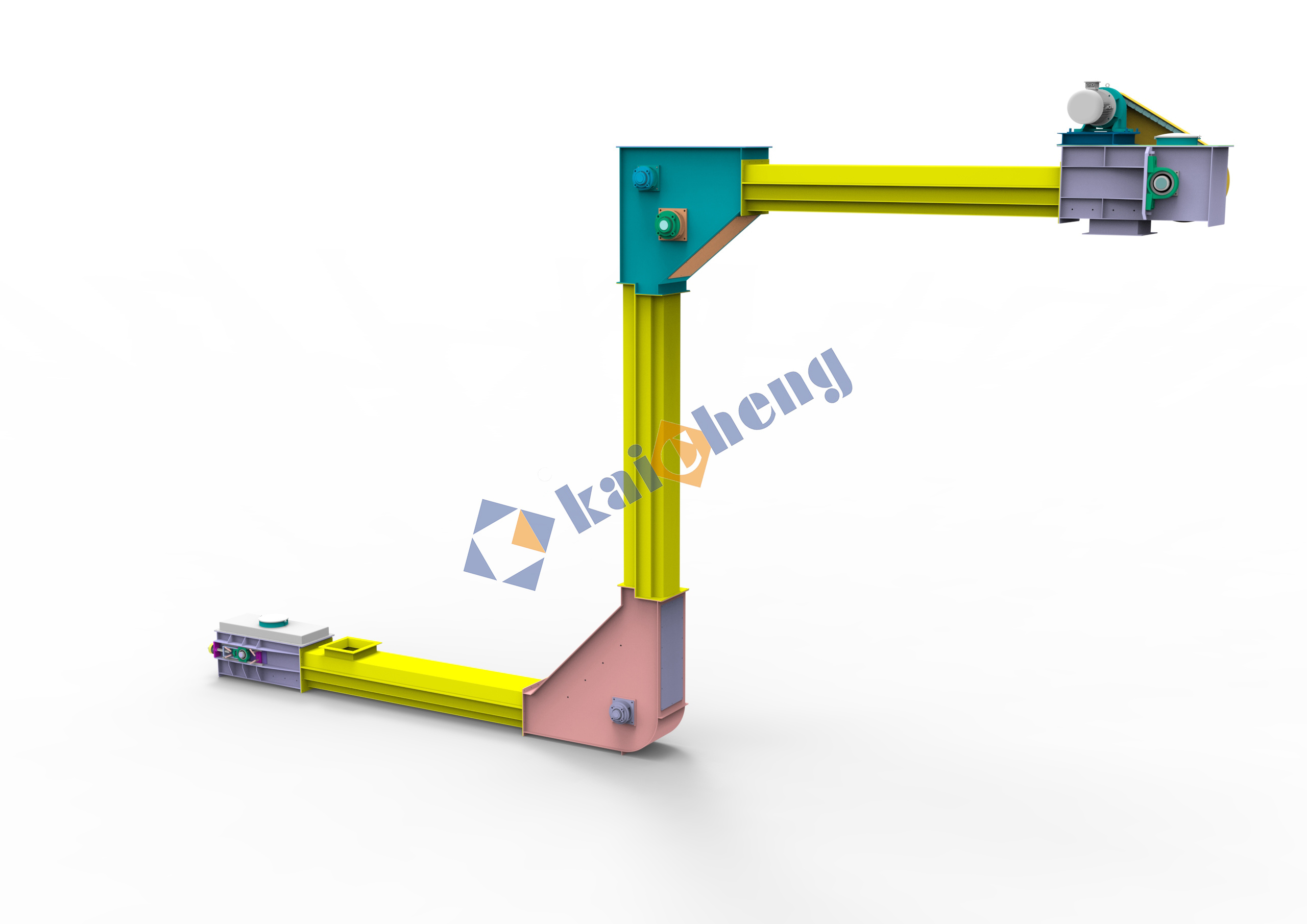
Spiral plate heat exchangers are used for liquid-to-liquid spiral heat exchangers. They have spiral curved channels, which can provide optimal heat transfer and flow conditions for various fluids. Models can be designed according to different conditions. diameter and heat transfer area.Working Principle:
The spiral heat exchanger has a double flow channel composed of two concentric spiral lines. The double flow channels do not interfere with each other, and the medium is in a completely counter-flow state in the flow channel. Thermal fluid generally enters from the central axis, flows from the inside to the outside, and flows out from the sides. The cold fluid enters from the outside of the side and flows inward toward the central axis to achieve counterflow. This method can achieve higher heat transfer coefficients than other types of heat exchangers. Easier to achieve temperature exchange.Equipment Advantages:
1. Efficient heat recovery is achieved through counter-current flow. The thermal efficiency is 2-3 times that of similar shell and tube heat exchangers, while reducing fossil fuel consumption and carbon dioxide emissions.
2. The single-channel design with self-cleaning effect significantly reduces scaling and lowers operating costs.
3. The easy-to-open design makes cleaning quick and simple, minimizing cleaning downtime and increasing production capacity.
4. The heat transfer surface is easy to inspect and clean.
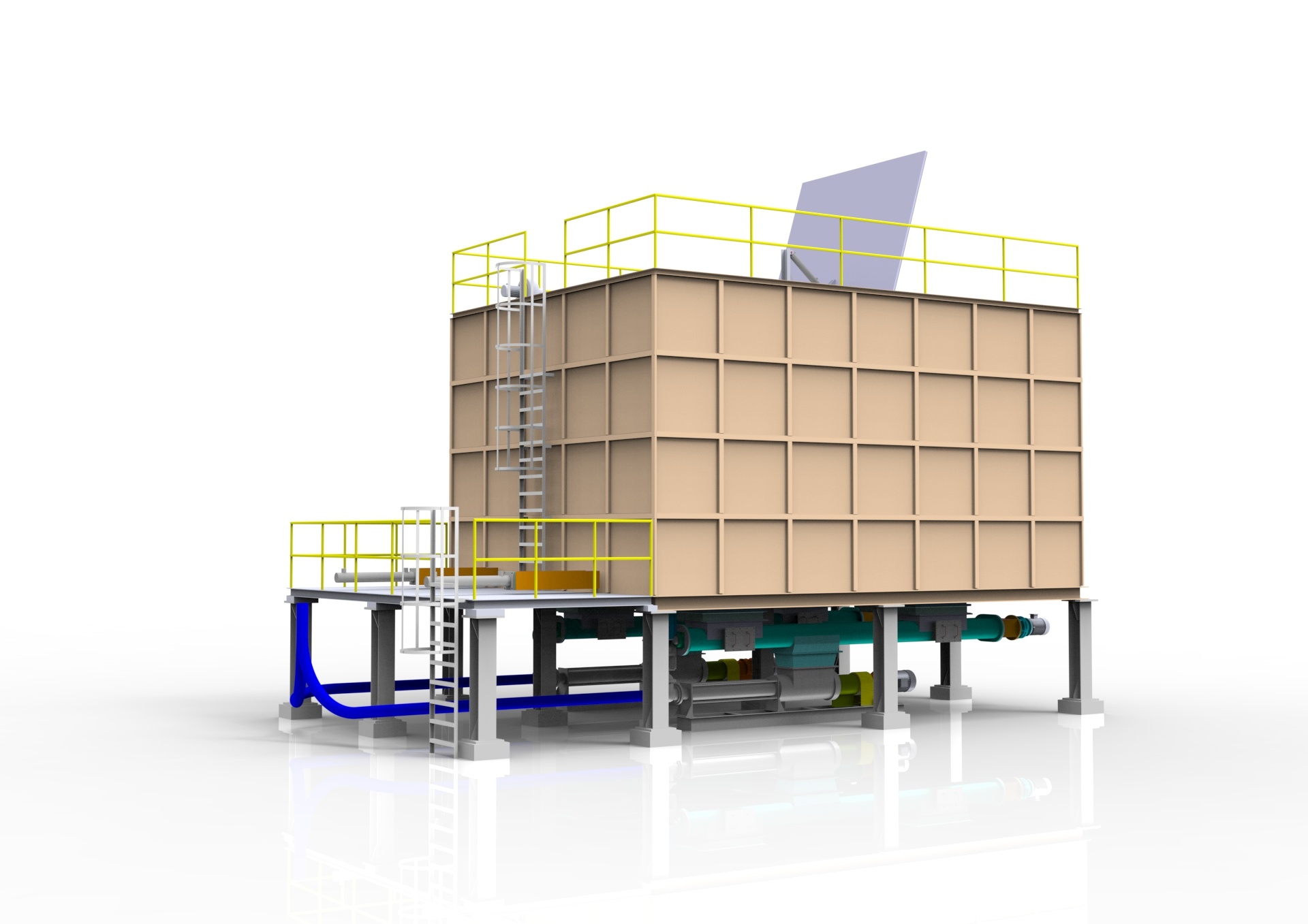
5. Compact and flexible design reduces pipeline engineering and steel structure, reduces installation and material costs, can be installed horizontally or vertically, saving annual maintenance budget.Application Industries:
- Petrochemical
- Refinery
- Steel manufacturing
- Pulp
- Mineral processing (metals, ores)
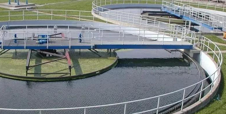
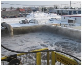
- Wastewater treatment (municipal and industrial)
- Pharmaceutical company
- Vegetable oil refining
- Natural gas processing
- Chemical slurry
-
-
-
Your May Also Like
leave A Message
We will contact you as soon as possible

Experts and Pioneers of Sludge Drying And Pyrolysis Field in China.


Contact
Location:1-208, Industrial Building, No. 555 North Panyu Avenue, Panyu District, Guangzhou, China